Why?
When working on previous projects I relied heavily on the ability to look into register values and to set breakpoints wherever I want. So being able to debug is a non-negotiable for my embedded projects. It just increases devvelopment speeds massively.
One downside of it is mostly the accessibility of the SWD connector. So when doing drone controllers, and other things that need to be protected by a case, you need to open the case every time you want to check something.
Recently I came across some stuff on hackaday which inspired me to put SWD and USB on a single USB-C connector. I tried this when working with the AxxSolder open source soldering iron and the feature really came in handy. You can start using the stuff you built without worrying about a way of updating and debugging when you come across bugs.
Since I really enjoy working with the J-Link and wanted to be able to try different debugging tools, I’ve decided to build an USB-C SWD injector first and maybe fo an integrated version in future. So having the programmer and the injector circuit on the same PCB.
How does it work?

text goes here …..

Reference voltage
Not all SWD debuggers incorporate level shifters and therefore make use of the VTref pin on the SWD connector. So when using an STLink no reference voltage is needed. Some of the J-Link models use built-in level shifters and need VTref for supplying the output level voltage to the shifters.
This is why I’ve decided to add an onboard 3.3V LDO and a small LED to see if the board is powered.
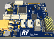
First version and its flaws
I built the first version for working on the AxxSolder. I designed the PCB quickly and got it manufactured by JLCPCB. the design is simple and the scope is clear, so what should possibly go wrong?
To good news: V1.0 worked fine for my flight controller designs but when testing it on AxxSolder I came across some things:
- I connected only one pair of the D+/D- lines
- I did not cross CC1 and CC2
- Used a 3.3V LDO with Vin of 6.5V to to provide the reference voltage for the J-Link
So I added some enamelled copper wire to fix D and CC.
When connecting a USB-PD power supply to the input, while debugging, the target did its job and negotiated 20V. Since my LDO was only able to 6.5V it started smoking. USB is usually 5.5V max but when using a type-C connector all sorts of other stuff can happen.
So I ended up re-doing the desing by fixing the USB-C connections and adding a 5V LDO (C78L05), which can handle up to 30V input voltage.